
Product
Support
0983029530
-


Mr, Linh Tran
+84983029530
Counter
Online : 1
Today's view : 33
Yesterday view : 74
Visited : 292961
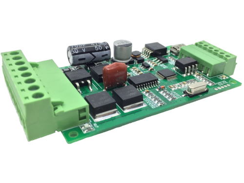
MSD_E20
6 Month


Feature
- 7 Segment Indicator.
- 10-40VDC, 0-20A, 1-600W.
- Position, Velocity, Acceleration Control.
- Autor Turning Tool Support.
- Follow Over Protect, Encoder, Motor Fail Protect.
- Over Current, Over Temperature, Short Circuit Protected.
- Support USB Communicate with DcTurningPro Sofware.
- Support Virtual Com Port to communicate with users.
- Communication: Pulse/Dir, UART, USB, Analog (Velocity Mode).
- Close Loop Support: Smart PID, PID, PI, State Feedback.
- H-Bridge mode with over current, temperature...protect.
Quantity
Introduce:
- The motion is very important and popular today. They appear in all most areas.
- Special the motor, that is a big part of this fill.
- There are many Dc Servo Drivers in the market but they are very special (not open), more expensive, so big...
- Our driver is very small, low cost, more friendly, more open.
- The driver has an Autor Turning Tool which auto-detect motor information.
- There are many communication methods Pulse/Dir, Uart Network, Virtual Com Port, Usb.
- There is software that can configure, control, simulate, visual.
Application:
- Evaluation Close Loop, Research.
- Robot, CNC, Automatic.
Demo:
1. Licenses ID:
Using this key HDHGILBOHFIEGDGN for DcTunerPro Software
2. Setting processing: (6 steps to config the Driver)
- Connect motor -> Encoder -> power to driver (Make sure correct power supply direction).
- Setting Encoder -> Save* -> Reset* (*: No need when config by the button)
- Turning (The driver will identify the Motor properties in this step)
- Choosing Mode Control: Position or Velocity
- Choosing Method Control: Pulse/Dir, Uart,...
- Save -> Reset.
3. Connection:
.png)
4. Mechanical Specification (unit: mm)

5. Config MSD_XX By Button:
Config Codes: (Keep pressing the Set_Button to Config Mode -> Short press the Set_Button to switch Code)
C0: Encoder Line C0 (Encoder Line of Motor = C0*100 + C1)
C1: Encoder Line C1 (Ex: Encoder 321 Pulse/Round <=> C0 =3; C1 = 21)
C2: Electronic Gear =C2*100 (Number of external pulses per one revolution.)
C3: Current limit (A)
C4: Control Modes (C4=0: Turning; C4=1: Velocity Control; C4=2: Position Control; C4=4: Hbridge or Open Loop)
C5: Control Methods (C5=0: Pulse/Dir; C5=1: Uart-Network; C5=3: potentiometer/Analog; C5=4: Usb to Com)
C6: Address of the driver in Uart-Network
C7: UART Baud Rate. (C7=0: 115220; C7=1: 57600; C7= 2: 19200).
F0: Number of rounds to run when the test button is pressed for the position control.
F1: Velocity setting for the test button. For example, F1:01 means 10 rads/second.
F2: Acceleration setting for the test button. For example, F2:01 means 100 rads/second2.
F3: Follow Error Value (rad) (difference between estimate position vs current position)
F4: Protection Flag (F4=0: Disable Protection feature; F4=1: Enable protection feature)
F8: Counter Pass ( F8 increase one value when every pass)
F9: Save settings. (F9=1: Saving & Reset; F9=2: Reset; F9=3: Factory Reset & Reset)
6. Pulse/Dir Communication: (Your MCU will genegray Pulse/Dir signal to control the driver)
7. Serial/Uart Communication: (Sending commands via Uart)
Uart Command List: ( Control Methods: UART/USB-UART (Vituar Com))
N0 ? : Help
Nx $xxx= Parameter_Value : Parameter Setting Group;
$001=20; Address of the Driver is: 20
$002=200; Encoder Line (Encoder resolution per Round)
$003=400; The main Motor Saft will run 1/400 circle per One Pulse from External Pin (Pul/Dir).
$004=4; Model Close Loop Type (0: Turning, 1: None, 2: PID Position, 3: PI Velocity (recommend), 4: Smart Position (recommend), 5: None, 6: H-Bridge mode (Working as H-Bridge))
$005=0; Communicate Methode (0: PULSE/DIR, 1: UART Network, 2: None, 3: Analog (Just for velocity Mode))
$006=2000mA; Current Limit
$007=12; Follow Error (rad(PositionModel) or rad/s(VelocityModel)): The Maximum different betwean ExtimateValue vs RealValue is 12
$008=1; Motor Protection Active (0: Disable, 1: Enable)
$009=115200; Uart Baudrate
$010=2; Delta Position Expect When press the TEST Button (Circle)
$011=60; Velocity Expect When press the TEST Button (Round/s)
$012=500; Acceleration Expect When press the TEST Button (Round/s2)
$020=4870; Kp_P=4870
$021=0; Ki_P=0
$022=69; Kd_P=69
$023=33; Kp_V=33
$024=1144; Ki_V=1144
$025=0; Kd_V=0
$026=0; Kp_I=0
$027=0; Ki_I=0
$028=0; Kd_I=0
$101=0; MCU(0: Runing, 1: Saving & Reset; 2: Reset; 3: Factory Reset & Reset;)
Nx [p/P value] [v value] [a value] : Moving motor Nx with p/P,v,a parametter
Nx: x Adress Of Driver (0: Broadcast ; 1->99: Unicast)
p: Absolute Position Value (Option)
P: Relative Position Value (Option)
v: Velocity Value(Option)
a: Acceleration Value (Option)
Example: (The Driver 1 go to 100rad with Velocity 50rad/s and Acceleration 600rad/s2): N1 p100 v50 a600
Nx [d value] : d= Duty Cycle in H-Bridge Mode ($004 = 6); (Value Range: -900 to 900)
Note: "-": Direct =0 ; "1": Direct = 1 ;
Nx O [Kx] [T] [Mx] [Dx] [S] [L] [U] [r] [R101] [Gx] [C] ; (O: Operation Group Command)
[ ] : Option
Kx : Ack command respond (K1: Enable (default at start up MCU); K0: Disable
T: Turning The Motor
Mx: Control Method = M4 (M3: PI Velocity, M4: Smart Position, M5: None, M6: H-Bridge mode (Working as H-Bridge))
Dx: Communicate Methode = D0 (D0: PULSE/DIR, D1: UART Network, D2: None, D3: Analog (Just for velocity Mode))
S: Saving All Parameter
L: Loock/Pause/Stoop the Motor immediately
U: Unlook Motor
r: Reset the Current Position to 0
R101: Reset the driver
C: Clear error list
G: Get moving infor (G1: One Time; G3: Unitil Receive a New Data With Frequency Respond 5Hz; G255: One time with Randome Delay)
8. Error Codes:
E1: Follow error (so big difference between estimate position vs current position)
E2: A+ and B+ are wired in reverse. The user may solve this by swapping the A+ B+ connections or
motor’s wire connections.
E3: Faulty encoder. No signal from the encoder. The motor is stuck.
E4: Faulty motor wiring or just faulty motor in general.
E5: Over current detected.
E6: Voltage is out of range.
E7: Calibration fails. Unable to detect the properties of the motor.
E8: Temperature is too high.
9. Install Software & Driver: (using DcTunerPro to config the driver)
- Install the driver from ".INF" file :
- Fix issues "The third-party INF does not contain digital signature information":
- Install DcTunerPro.
US:
-
Makermotor: https://makermotor.com/cc-smart/
-
RobotShop: robotshop.com
Other Products

Working Voltage: 10-40VDC
Continuous Current: Up To 10A
Power Max: 200W
Quantity: 300

Working Voltage : 8-40VDC
Continuous Current: Up To 10A
Power Max: 200W
Quantity: 199

Working Voltage: 10-40VDC
Continuous Current: Up To 20A
Power Max: 600W
Quantity: 180

Working Voltage: 6-30VDC
Continuous Current: Up To 3A
Power Max: 30W
Quantity: 294

Working Voltage: 10-40VDC
Continuous Current: Up To 10A
Power Max: 280W
Quantity: 240
Operation Voltage: 10-30/40DCV
Max Continous Current: 20
Max Power: 400W
Quantity: 3